Page History
...
If µ and B / (n * H) is 0.3 at accelerations sideways at transport in sea area B (cy = 0.7 g) the cargo securing arrangement should be able to be inclined to approximately 39º, according to the diagram.
In the table below the inclination α is calculated for different γ factors at the horizontal accelerations (cx,y = 0.8 g, 0.7 g and 0.5 g and cz = 1.0 g).
The γ factor is defined as follows:
µ, B/(n · H) and L/H, as required in section 4 of this appendix.
ah γ factor | 0.8 g | 0.7 g | 0.5 g |
Required test angle α in degrees | |||
0.00 | 53.1 | 44.4 | 30.0 |
0.05 | 51.4 | 43.3 | 29.6 |
0.10 | 49.9 | 42.4 | 29.2 |
0.15 | 48.5 | 41.5 | 28.8 |
0.20 | 47.3 | 40.7 | 28.4 |
0.25 | 46.3 | 39.9 | 28.1 |
0.30 | 45.3 | 39.2 | 27.7 |
0.35 | 44.4 | 38.6 | 27.4 |
0.40 | 43.6 | 38.0 | 27.1 |
0.45 | 42.8 | 37.4 | 26.8 |
0.50 | 42.1 | 36.9 | 26.6 |
0.55 | 41.5 | 36.4 | 26.3 |
0.60 | 40.8 | 35.9 | 26.0 |
0.65 | 40.2 | 35.4 | 25.8 |
0.70 | 39.7 | 35.0 | 25.6 |
0.75 | 39.2 | 34.6 | 25.3 |
0.80 | 38.7 | 34.2 | 25.1 |
0.85 | 38.2 | 33.8 | 24.9 |
0.90 | 37.7 | 33.4 | 24.7 |
0.95 | 37.3 | 33.1 | 24.5 |
1.00 | 36.9 | 32.8 | 24.3 |
...
6 The securing arrangement is regarded as complying with the requirements if the cargo is kept in position with limited movements when inclined to the prescribed inclination α.
7 The test method will subject the securing arrangement to stresses and great care should be taken to prevent the cargo from falling off the platform during the test. If large masses are to be tested the entire platform should be prevented from tipping as well.
Figure 7.64 | Figure 7.65 |
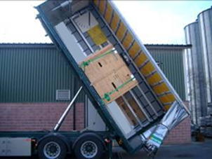
8 Figure 7.64 and figure 7.65 show tests to confirm the securing arrangements of a large package for acceleration forces in longitudinal and transverse directions.

