4.1 Aims and principles of securing
4.1.1 Arrangements or stacks of cargo items should be packed in a way so as not to deform and to remain in place and upright with no tilting by their static friction and by their inherent stability, while packing or unpacking a CTU is in progress. This guarantees the safety of packers before additional securing devices are put in place or after such devices have been removed for unpacking.
4.1.2 During transport the CTU may be subjected to vertical, longitudinal and transverse accelerations, which cause forces to each cargo item, which are proportional to its mass. It should not be assumed, that because a package is heavy, it will not move during transport. The relevant accelerations are outlined in chapter 5 of this Code in units of g, indicating the corresponding forces in units of weight of the distinguished cargo item. These forces may easily exceed the capability of static friction and tilting stability, so that cargo items may slide or tilt over. In addition, the CTU may be simultaneously subjected to temporary vertical accelerations, which cause a weight decrease, thereby reduce the friction and the inherent tilting stability, thus promoting sliding and tipping. Any securing of cargo should aim at the avoidance of such unwanted cargo behaviour. All parts of the cargo should remain in place and neither slide nor tip under the stipulated accelerations of the CTU during the intended route of transport.
4.1.3 Practical securing of cargo may be approached by three distinguished principles, which may be used individually or combined as appropriate:
- Direct securing is effected by the immediate transfer of forces from the cargo to the CTU by means of blocking, lashings, shores or locking devices. The securing capacity is proportional to the MSL of the securing devices;
- Friction securing is achieved by so-called tie-down or top-over lashings which, by their pre-tension, increase the apparent weight of the cargo and thereby the friction to the loading ground and also the tilting stability. The securing effect is proportional to the pre-tension of the lashings. Anti-slip material in the sliding surfaces considerably increases the effect of such lashings;
- Compacting cargo by bundling, strapping or wrapping is an auxiliary measure of securing that should always be combined with measures of direct securing or friction securing.
4.1.4 Lashings used for direct securing will inevitably elongate under external forces, thus permitting the package a degree of movement. To minimize this movement, (horizontal or lateral sliding, tipping or racking) it should be ensured that the:
- Lashing material has appropriate load-deformation characteristics (see section 2.4 of this annex);
- Length of the lashing is kept as short as practicable; and
- Direction of the lashing is as close as possible to the direction of the intended restraining effect.
A good pre-tension in lashings will also contribute to minimizing cargo motions, but the pre-tension should never exceed 50% of the MSL of the lashing. Direct securing by stiff pressure elements (shores or stanchions) or by locking devices (locking cones or twist-locks) will not allow significant cargo motion and should therefore be the preferred method of direct securing.
4.1.5 Lashings used for friction securing should be able to maintain the vital pre-tension for a longer period and should not fall slack from minor settling or shrinking of the cargo. Therefore synthetic fibre web lashings should be preferred to e.g. chains or steel band lashings. The pre-tension of tie-down lashings does in principle not fall under the limitation stated above for direct lashings, but will generally not be greater than 20% of the MSL of the lashing with manually operated tensioners. Care should be taken to establish this pre-tension on both sides of the lashing as far as is practical. For assessing a friction securing arrangement by calculation, the labelled standard pre-tension[1] should be used. If such marking is not available, a rule of thumb value of 10% of the breaking strength of the lashing, but not more than 10 kN, should be used for calculation.
4.1.6 Arrangements of direct securing devices should be homogeneous in a way that each device in the arrangement takes its share of the restraining forces appropriate to its strength. Unavoidable differences in load distribution within complex arrangements may be compensated for by the application of a safety factor. Nevertheless, devices of diverging load-deformation properties should not be placed in parallel, unless used for the distinguishable purposes of sliding prevention and tipping prevention. If, for instance, timber blocking and direct web lashing is used in parallel against sliding, the stiffer timber blocking should be dimensioned so as to resist the expected load alone. This restriction does not apply to the combination of tie-down lashings and e.g. timber blocking.
4.1.7 Any cargo securing measures should be applied in a manner that does not affect, deform or impair the package or the CTU. Permanent securing equipment incorporated into a CTU should be used whenever possible or necessary.
4.1.8 During transport, in particular at suitable occasions of a multimodal transport route, securing arrangements in CTUs should be checked and upgraded if necessary and as far as practicable. This includes re-tightening of lashings and wire rope clips and adjusting of blocking arrangements.
4.2 Tightly arranged cargoes
4.2.1 A vital prerequisite of cargo items for a tight stowage arrangement is their insensibility against mutual physical contact. Cargo parcels in form of cartons, boxes, cases, crates, barrels, drums, bundles, bales, bags, bottles, reels etc. or pallets containing the aforesaid items are usually packed into a CTU in a tight arrangement in order to utilize the cargo space, to prevent cargo items from tumbling around and to enable measures of common securing against transverse and longitudinal movement during transport.
4.2.2 A tight stow of uniform or variable cargo items should be planned and arranged according to principles of good packing practice, in particular observing the advice given in section 3.2 of this annex. If coherence between items or tilting stability of items is poor, additional measures of compacting may be necessary like hooping or strapping batches of cargo items with steel or plastic tape or plastic sheeting. Gaps between cargo items or between cargo and CTU boundaries should be filled as necessary (see subsections 2.3.6 to 2.3.8 of this annex). Direct contact of cargo items with CTU boundaries may require an interlayer of protecting material (see section 2.1 of this annex).
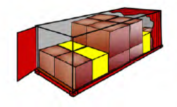
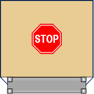
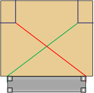
Figure 7.29 Packing 1,000 x 1,200 mm unit loads into a 20-foot container |
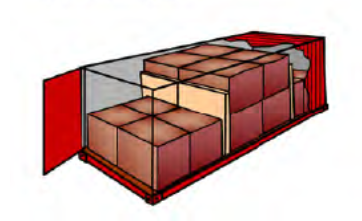
Figure 7.30 Packing 800 x 1,200 mm unit loads into a 20-foot container |
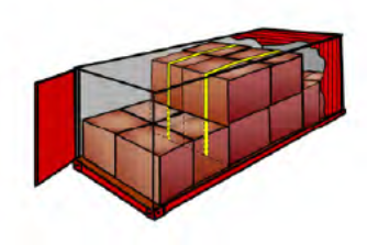
Figure 7.31 Packing 1,000 x 1,200 mm unit loads into a 40-foot container | |
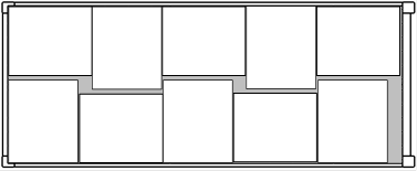
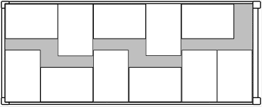

Note: The void areas (grey shaded) shown in figures 7.29 to 7.31 should be filled when necessary (see subsection 2.3.6 of this annex)
4.2.3 CTUs with strong cargo space boundaries may inherently satisfy transverse and longitudinal securing requirements in many cases, depending on the type of CTU, the intended route of transport and appropriate friction among cargo items and between cargo and stowage ground. The following balance demonstrates the confinement of tightly stowed cargo within strong cargo space boundaries:
[kN] | |
cx,y = | horizontal acceleration coefficient in the relevant mode of transport (see chapter 5 of this Code) |
m = | mass of cargo packed [t] |
g = | gravity acceleration 9.81 m/s2 |
rx,y = | CTU wall resistance coefficient (see chapter 6 of this Code) |
P = | maximum payload of CTU (t) |
µ = | applicable friction factor between cargo and stowage ground (see appendix 2 to this annex) |
cz = | vertical acceleration coefficient in the relevant mode of transport (see chapter 5 of this Code) |
|
|
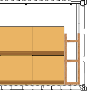
4.2.4 Critical situations may arise, e.g. with a fully packed freight container in road transport, where longitudinal securing should be able to withstand an acceleration of 0.8 g. The longitudinal wall resistance factor of 0.4should be combined with a friction factor of at least 0.4 for satisfying the securing balance. If a balance cannot be satisfied, the mass of cargo should be reduced or the longitudinal forces transferred to the main structure of the container. The latter can be achieved by intermediate transverse fences of timber battens (see subsection 2.3.4 of this annex) or by other suitable means (see figure 7.32). Another option is the use of friction increasing material.
Side View |
End View |
Plan view |
|
Figure 7.32 Blocking in a strong boundary CTU | |

4.2.5 When the door end of a CTU is designed to provide a defined wall resistance (e.g. the doors of a general purpose freight container (see chapter 6 of this Code), the doors may be considered as a strong cargo space boundary, provided the cargo is stowed to avoid impact loads to the door end and to prevent the cargo from falling out when the doors are opened.
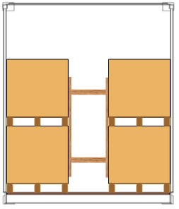
4.2.6 Where there is the need to stack packages in an incomplete second layer at the centre of the CTU, additional longitudinal blocking can be adopted (see figures 7.33 to 7.36).
Figure 7.33 Threshold by height |
Figure 7.34 Threshold by elevation |
Figure 7.35 Threshold by board |
Figure 7.36 Round turn lashing |

4.2.7 CTUs with weak cargo space boundaries like certain road vehicles and swap bodies will regularly require additional securing measures against sliding and tipping of a block of tightly stowed cargo. These measures should also contribute to compacting the block of cargo. The favourite method in this situation is friction-securing by so-called top-over lashings. For obtaining a reasonable securing effect from friction lashings, the friction factor between cargo and stowage ground should be sufficient and the inherent elasticity of the lashings should be able to maintain the pre-tension throughout the course of transport. The following balance demonstrates the confinement of tightly stowed cargo within weak cargo space boundaries and an additional securing force against sliding:
 [kN] (Fsec = additional securing force)
If a wall resistance coefficient is not specified for the distinguished CTU, it should be set to zero. The additional securing (Fsec) may consist of blocking the base of the cargo against stronger footing of the otherwise weak cargo space boundary or bracing the block of cargo against stanchions of the cargo space boundary system. Such stanchions may be interconnected by pendants above the cargo for increasing their resistance potential. Alternatively, the additional securing force may be obtained by direct securing methods or top-over lashings. Fsec per top-over lashing is: FV ∙ µ, where FV is the total vertical force from the pre-tension. For vertical lashings FV is 1.8 times the pre-tension in the lashing. For direct lashing arrangements µ should be set to 75% of the friction factor.
4.2.8 On CTUs without boundaries the entire securing effect should be accomplished by securing measures like top-over lashings, friction increasing material and, if the CTU is a flatrack, by longitudinal blocking against the end-walls. The following balance demonstrates the securing of tightly stowed cargo on a CTU without cargo space boundaries:
 [kN] (Fsec = additional securing force)
For Fsec, see subsection 4.2.7. It should be noted that even in case of a friction factor that outnumbers the external acceleration coefficients, without cargo space boundaries a minimum number of top-over lashings is imperative for avoiding migration of the cargo due to shocks or vibration of the CTU during transport.
4.3 Individually secured packages and large unpackaged articles
4.3.1 Packages and articles of greater size, mass or shape or units with sensitive exterior facing, which does not allow direct contact to other units or CTU boundaries, should be individually secured. The securing arrangement should be designed to prevent sliding and, where necessary, tipping, both in the longitudinal and transverse direction. Securing against tipping is necessary, if the following condition is true (see also figure 7.37):
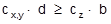 | |
cx,y = | horizontal acceleration coefficient in the relevant modes of transport (see chapter 5 of this Code) |
d= | vertical distance from centre of gravity of the unit to its tipping axis [m] |
cz = | vertical acceleration coefficient in the relevant modes of transport (see chapter 5 of this Code) |
b = | horizontal distance from centre of gravity to tipping axis [m] |
Figure 7.37 Tipping criterion | |

4.3.2 Individually secured packages and articles should preferably be secured by a direct securing method, i.e. by direct transfer of securing forces from the package to the CTU by means of lashings, shores or blocking.
4.3.2.1 A direct lashing will be between fixed fastening points on the package/article and the CTU and the effective strength of such a lashing is limited by the weakest element within the device, which includes fastening points on the package as well as fastening points on the CTU.
4.3.2.2 For sliding prevention by lashings the vertical lashing angle should preferably be in the range of 30° to 60° (see figure 7.38). For tipping prevention the lashings should be positioned in a way that provides effective levers related to the applicable tipping axis (see figure 7.39).
Figure 7.38 Direct lashing against sliding |
Figure 7.39 Direct lashing against tipping |


4.3.3 Packages and articles without securing points should be either secured by shoring or blocking against solid structures of the CTU or by top-over, half-loop or spring lashings (see figures 7.40 to 7.43).
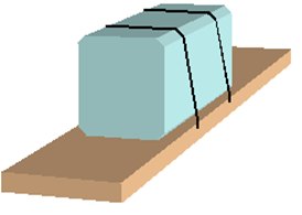
Figure 7.40 Top over lashing | |
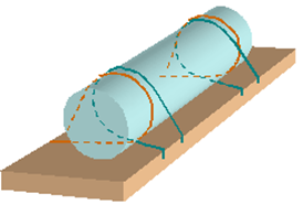
Figure 7.41 Vertical half-loop lashing |
Figure 7.42 Horizontal half-loop lashing |
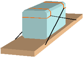
Figure 7.43 Spring lashing |
Figure 7.44 Silly-loop lashing |

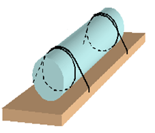
4.3.3.1 Loop lashings with their ends fastened to either side (see figure 7.44), also called "silly-loops", do not provide any direct securing effect and may permit the package/article to roll and therefore are not recommended
4.3.3.2 Lashing corner fittings are available to provide alternative lashing to the spring lashing (see figure 7.43).
4.3.3.3 Any lashing method adopted will require that the lashing material stretches in order to develop a restraining force. As the material relaxes, the tension in the lashing will slowly reduce, therefore it is important that the guidance given in subsection 4.1.4 of this annex should be followed.
4.3.4 CTUs with strong cargo space boundaries favour the method of blocking or shoring for securing a particular package or article. This method will minimize cargo mobility. Care should be taken that the restraining forces are transferred to the CTU boundaries in a way that excludes local overloading. Forces acting to CTU walls should be transferred by means of load spreading cross beams (see subsections 2.3.1 to 2.3.3 of this annex). Very heavy packages or articles, e.g. steel coils or blocks of marble, may require a combination of blocking and lashing, however with observation of the restrictions lined out in subsection 4.1.6 of this annex (see figure 7.45). Articles with sensitive surfaces may rule out the blocking method and should be secured by lashings only.
Figure 7.45 Transverse blocking of steel slab |

4.3.5 Individual securing of packages or articles in CTUs with weak cargo space boundaries and in CTUs without boundaries requires predominantly the method of lashing. Where applicable, blocking or shoring may be additionally applied, but if used in parallel with lashings, the restrictions set out in subsection 4.1.6 of this annex should be observed. Although the provision of good friction in the bedding of a package or article is recommended in any case, the use of top-over lashings for sliding prevention is discouraged unless the cargo has limited mass. Top-over lashings may be suitable for tipping prevention. In particular over-width packages or articles, often shipped on flat bed CTUs, should not be secured solely by top-over lashings (see figure 7.46). The use of half loops and/or spring lashings is strongly recommended (see figures 7.47 and 7.48).
Figure 7.46 Top-over lashing |
Figure 7.47 Top-over and horizontal half-loop |
Figure 7.48 Transverse spring lashing |

4.3.6 Where horizontal half loops are used, a means should be provided to prevent the loops from sliding down the package/article.
4.3.7 Alternatively an over-width package or article can be secured by half-loops over the corners as shown in figure 7.49.
Figure 7.49 Over-width package secured by half-loops |

4.4 Evaluation of securing arrangements
4.4.1 Evaluation of securing arrangements means making up a balance of expected external forces and moments against the securing potential of the planned or implemented securing arrangement. Expected external forces should be determined by multiplying the applicable acceleration coefficient, given in chapter 5 of this Code, with the weight of the package or block of packages in question.
| |
Fx,y = | expected external force [kN] |
m = | mass of cargo to be evaluated [t] |
g = | gravity acceleration 9.81m/s2 |
cx,y = | horizontal acceleration coefficient in the relevant mode of transport (see chapter 5 of this Code) |

Chapter 5 distinguishes three modes of transport, road, rail and sea. The sea transport mode is further subdivided into three categories of severity of ship motions, aligned to the significant wave height of distinguished sea areas. Therefore the selection of the applicable acceleration factor requires the full information on the intended mode and route of transport. Due consideration should be given to possible multimodal transport, in order to identify the acceleration figures for the most demanding mode or leg of the transport route. These figures should be finally used for the evaluation of the securing arrangement.
4.4.2 The assessment of the securing potential includes the assumption of a friction factor, based on the combination of materials (see appendix 2 to this annex) and the character of the securing arrangement (subsection 2.2.2 of this annex), and, if applicable, the determination of the inherent tilting stability of the cargo (subsection 4.3.1 of this annex). Any other securing devices used for blocking, shoring or lashing should be estimated by their strength in terms of MSL and relevant application parameters like securing angle and pre-tension. These figures are required for evaluating the securing arrangement.
4.4.3 In many cases the evaluation of a securing arrangement may be accomplished by means of a simple rule of thumb. However, such rules of thumb may be applicable for certain distinguished conditions of transport only, e.g. for sea transport, and may overshoot or fall short in other conditions. It is therefore advisable to phrase such rules of thumb for distinguished modes of transport and use them accordingly. Any phrasing of a rule of thumb should undergo a first-time check by means of an advanced assessment method.
4.4.4 Standardized assessment methods for the evaluation of securing arrangements may consist of appropriate pre-calculated tables, based on balance calculations, which give quick answers regarding the adequacy of a securing arrangement[2]. Such methods may be directed to specific modes of transport.
4.4.5 Evaluation of securing arrangements may be carried out by balancing forces and moments by an elementary calculation. However, the particular method used should be approved and suitable for the intended purpose and mode of transport. Specific guidance may be found in the IMO Code of Safe Practice for Cargo Stowage and Securing (CSS Code) and in various other standards and guidelines issued by regional or national authorities and industry groups covering various modes of transport. References:
- IMO CSS Code, Annex 13, for sea transport;
- European standard EN 12195-1:2010, for road transport;
- International Union of Railways (UIC), Agreement governing the exchange and use of wagons between Railway Undertakings (RIV 2000) Annex II, for rail transport.
4.4.6 The suitability of a specific securing arrangement may be evaluated and approved by an inclination test. The test may be used to demonstrate resistance against any specified external acceleration. The corresponding test-angle depends on the existing friction factor for a sliding resistance test, or on the relation between the height and the width of cargo for a tipping resistance test (see appendix 5 to this annex).
[1] Standard tension force STF according to EN 12195-2
[2] One of the assessment methods is the Quick Lashing Guide that can be found in informative material IM 5 (available at www.unece.org/trans/wp24/guidelinespackingctus/intro.html).
Overview
Content Tools
Apps
Intermodal Transport![]()
UNECE Transport Division