1 The efficiency of a securing arrangement can be tested by a practical inclining test in accordance with the following description.
2 The cargo (alternatively one section of the cargo) is placed on a road vehicle platform or similar and secured in the way intended to be tested.
3 To obtain the same loads in the securing arrangement in the inclining test as in calculations, the securing arrangement should be tested by gradually increasing the inclination of the platform to an angle, α, in accordance with the diagram below.
4 The inclination angle that should be used in the test is a function of the horizontal acceleration cx,y for the intended direction (forward, sideways or backward) and the vertical acceleration cz.
(a) To test the efficiency of the securing arrangement in the lateral direction, the greatest of the following test angles should be used:
- The angle determined by the friction factor µ (for the sliding effect), or
- The angle determined by the ratio of B / (n * H) (for the tilting effect).
(b) To test the efficiency of the securing arrangement in the longitudinal direction, the greatest of following test angles should be used:
- The angle determined by the friction factor µ (for the sliding effect), or
- The angle determined by the ratio of L / H (for the tilting effect).
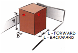
5 The lowest friction factor, between the cargo and the platform bed or between packages if over-stowed should be used. The definition of H, B, L and n is according to the sketches in figures 7.61 and 7.62.
Figure 7.61 |
Figure 7.62 |
Package or section with the centre of gravity close to its geometrical centre (L/2, B/2, H/2). The number of loaded rows, n, in above section is 2. L is always the length of one section also when several sections are placed behind each other. | Package with the centre of gravity away from its geometrical centre. |

The required test angle α as function of cx,y (0.8 g, 0.7 g and 0.5 g ) as well as µ, B / (n * H) and L / H when cz is 1.0 g is taken from the diagram shown in figure 7.63 or from the table below.
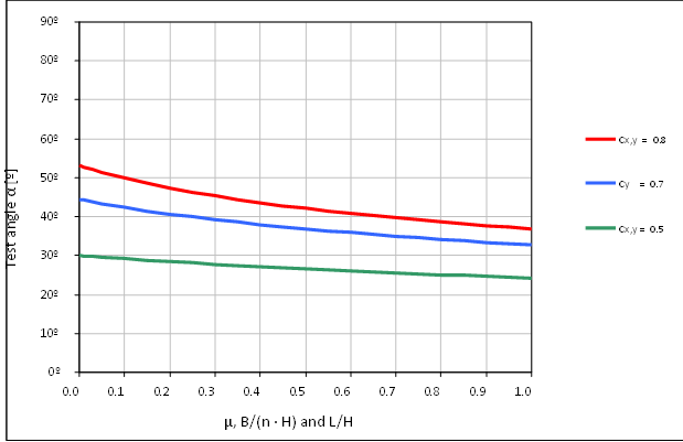
Figure 7.63
Example:
If µ and B / (n * H) is 0.3 at accelerations sideways at transport in sea area B (cy = 0.7 g) the cargo securing arrangement should be able to be inclined to approximately 39º, according to the diagram.
In the table below the inclination α is calculated for different γ factors at the horizontal accelerations (cx,y = 0.8 g, 0.7 g and 0.5 g and cz = 1.0 g).
The γ factor is defined as follows:
µ, B/(n · H) and L/H, as required in section 4 of this appendix.
ah γ factor | 0.8 g | 0.7 g | 0.5 g |
Required test angle α in degrees | |||
0.00 | 53.1 | 44.4 | 30.0 |
0.05 | 51.4 | 43.3 | 29.6 |
0.10 | 49.9 | 42.4 | 29.2 |
0.15 | 48.5 | 41.5 | 28.8 |
0.20 | 47.3 | 40.7 | 28.4 |
0.25 | 46.3 | 39.9 | 28.1 |
0.30 | 45.3 | 39.2 | 27.7 |
0.35 | 44.4 | 38.6 | 27.4 |
0.40 | 43.6 | 38.0 | 27.1 |
0.45 | 42.8 | 37.4 | 26.8 |
0.50 | 42.1 | 36.9 | 26.6 |
0.55 | 41.5 | 36.4 | 26.3 |
0.60 | 40.8 | 35.9 | 26.0 |
0.65 | 40.2 | 35.4 | 25.8 |
0.70 | 39.7 | 35.0 | 25.6 |
0.75 | 39.2 | 34.6 | 25.3 |
0.80 | 38.7 | 34.2 | 25.1 |
0.85 | 38.2 | 33.8 | 24.9 |
0.90 | 37.7 | 33.4 | 24.7 |
0.95 | 37.3 | 33.1 | 24.5 |
1.00 | 36.9 | 32.8 | 24.3 |
6 The securing arrangement is regarded as complying with the requirements if the cargo is kept in position with limited movements when inclined to the prescribed inclination α.
7 The test method will subject the securing arrangement to stresses and great care should be taken to prevent the cargo from falling off the platform during the test. If large masses are to be tested the entire platform should be prevented from tipping as well.
Figure 7.64 |
Figure 7.65 |


8 Figure 7.64 and figure 7.65 show tests to confirm the securing arrangements of a large package for acceleration forces in longitudinal and transverse directions.
Overview
Content Tools
Apps
Intermodal Transport![]()
UNECE Transport Division