Page History
...
4.1.2 During transport the CTU may be subjected to vertical, longitudinal and transverse accelerations, which cause forces to each cargo item, which are proportional to its mass. It should not be assumed, that because a package is heavy, it will not move during transport. The relevant accelerations are outlined in chapter 5 of this Code in units of g, indicating the corresponding forces in units of weight of the distinguished cargo item. These forces may easily exceed the capability of static friction and tilting stability, so that cargo items may slide or tilt over. In addition, the CTU may be simultaneously subjected to temporary vertical accelerations, which cause a weight decrease, thereby reduce the friction and the inherent tilting stability, thus promoting sliding and tipping. Any securing of cargo should aim at the avoidance of such unwanted cargo behaviour. All parts of the cargo should remain in place and neither slide nor tip under the stipulated accelerations of the CTU during the intended route of transport.
...
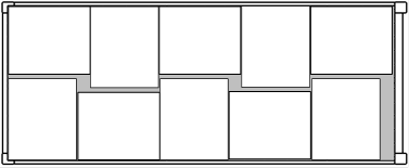
Figure 7.29 Packing 1,000 x 1,200 mm unit loads loads into a 20-foot container |
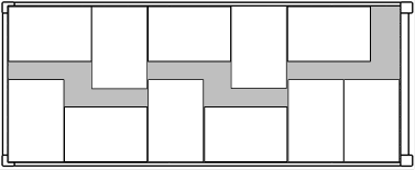
Figure 7.30 Packing 800 x 1,200 mm unit loads into a 20-foot container |
Figure 7.31 Packing 1,000 x 1,200 mm unit loads into a 40-foot container | |

...
[kN] | |
cx,y = | horizontal acceleration coefficient in the relevant mode of transport (see chapter 5 of this Code) |
m = | mass of cargo packed [t] |
g = | gravity acceleration 9.81 m/s2 |
rx,y = | CTU wall resistance coefficient (see chapter 6 of this Code) |
P = | maximum payload of CTU (t) |
µ = | applicable friction factor between cargo and stowage ground (see appendix 2 to this annex) |
cz = | vertical acceleration coefficient in the relevant mode of transport (see chapter 5 of this Code) |
|
|
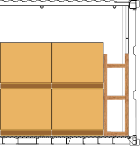
4.2.4 Critical situations may arise, e.g. with a fully packed freight container in road transport, where longitudinal securing should be able to withstand an acceleration of 0.8 g. The longitudinal wall resistance factor of 0.4should be combined with a friction factor of at least 0.4 for satisfying the securing balance. If a balance cannot be satisfied, the mass of cargo should be reduced or the longitudinal forces transferred to the main structure of the container. The latter can be achieved by intermediate transverse fences of timber battens (see subsection 2.3.4 of this annex) or by other suitable means (see figure 7.32). Another option is the use of friction increasing material.
Side View |
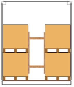
End View |
Plan view |
|
Figure 7.32 Blocking in a strong boundary CTU | |

4.2.5 When the door end of a CTU is designed to provide a defined wall resistance (e.g. the doors of a general purpose freight container (see chapter 6 of this Code), the doors may be considered as a strong cargo space boundary, provided the cargo is stowed to avoid impact loads to the door end and to prevent the cargo from falling out when the doors are opened.
...
For Fsec, see subsection 4.2.7. It should be noted that even in case of a friction factor that outnumbers the external acceleration coefficients, without cargo space boundaries a minimum number of top-over lashings is imperative for avoiding migration of the cargo due to shocks or vibration of the CTU during transport.
...
4.4.1 Evaluation of securing arrangements means making up a balance of expected external forces and moments against the securing potential of the planned or implemented securing arrangement. Expected external forces should be determined by multiplying the applicable acceleration coefficient, given in chapter 5 of this Code, with the weight of the package or block of packages in question.
| |
Fx,y = | expected external force [kN] |
m = | mass of cargo to be evaluated [t] |
g = | gravity acceleration 9.81m/s2 |
cx,y = | horizontal acceleration coefficient in the relevant mode of transport (see chapter 5 of this Code) |

Chapter 5 distinguishes three modes of transport, road, rail and sea. The sea transport mode is further subdivided into three categories of severity of ship motions, aligned to the significant wave height of distinguished sea areas. Therefore the selection of the applicable acceleration factor requires the full information on the intended mode and route of transport. Due consideration should be given to possible multimodal transport, in order to identify the acceleration figures for the most demanding mode or leg of the transport route. These figures should be finally used for the evaluation of the securing arrangement.
...
4.4.5 Evaluation of securing arrangements may be carried out by balancing forces and moments by an elementary calculation. However, the particular method used should be approved and suitable for the intended purpose and mode of transport. Specific guidance may be found in the IMO Code of Safe Practice for Cargo Stowage and Securing (CSS Code) and in various other standards and guidelines issued by regional or national authorities and industry groups covering various modes of transport. References:
- IMO CSS Code, Annex 13, for sea transport;
- European standard EN 12195-1:2010, for road transport;
- International Union of Railways (UIC), Agreement governing the exchange and use of wagons between Railway Undertakings (RIV 2000) Annex II, for rail transport.
...
Overview
Content Tools
Apps